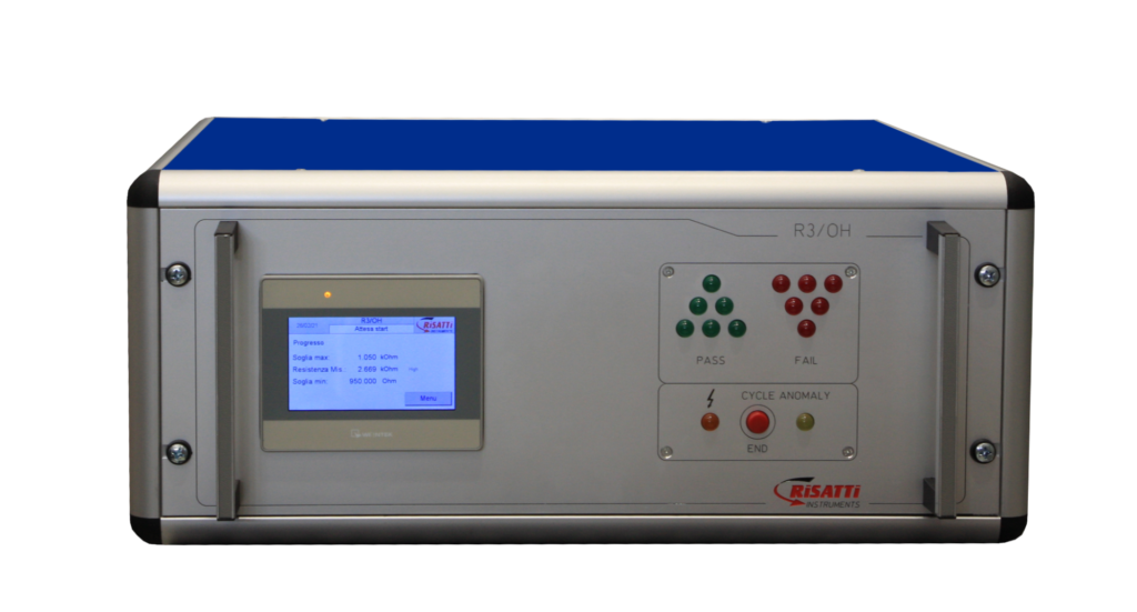
Up to 10 tests in a single, easily trasportable tool.
TESTING:
- SURGE (EN 60034-15) ON 1-2-3 WINDINGS IN AUTOMATIC SEQUENCE 12kV-18kV-24kV
- DIELECTRIC STRENGTH IN D.C. 12kV-18kV-24kV
- INSULATION RESISTANCE 200-2,700 V. D.C. – 1 GΩ
- MILLIOHM METER WITH CALCULATION OF DELTA T AND IMBALANCE OF PHASES
- DIE CAST ROTOR TEST
- WOUND ROTOR TEST
- POLARIZATION INDEX – PI (Option)
- DIELECTRIC ABSORPTION RATIO – DAR (Option)
- DIELECTRIC DISCHARGE – DD (Option)
- PARTIAL DISCHARGES ON DIELECTRIC STRENGTH AND SURGE – PD-PDIV (Option-only upon commercial request)
OPTIONS:
- Incorporated 42-column printer
- O3/BPR sensor for die-cast rotors
- Tool for testing wound rotors with start pedal
- Folding instrument-holder carriage
- WIFI connection
- Automatic sequence for the first 4 tests
| PC PANEL | |
| PANEL PC | MONITOR 10” |
| PROCESSOR | INTEL BAYTRAIL QUAD CORE 1,9 GHz FANLESS |
| RAM | 4 GB |
| HARD DISK | 64Gb extractable solid state (SSD) |
| WINDOWS | WINDOWS 10 Iot |
| No. 5 | 3 USB ports 2.0 (+2 frontal) |
| No. 1 | VGA |
| No. 2 | LAN ETHERNET 10/100/1000 Mbps |
| No. 3 | N. 2 RS232 – N.1 RS232/422/485 |
| UPS | 24Vdc with integrated UPS unit |
| BACKLIGHTED DISPLAY | LED 10.4” TFT, 16M colours, 800X600 TOUCH SCREEN, resistive with 8 wires |
| REMOTE SERVICE ASSISTANCE | Possibility of technical assistance with TEAM VIEWER
(internet connection not provided) |
OTHER FEATURES
- Memorisation of the set data and results for each single test with the relating response curves
- Indication of the test result using GREEN-RED signals on the display
- Development software with LABVIEW graphic menu from National Instruments.
- Double START button with anti-repetitive
- Selection of the test using the display
OHMIC RESISTANCE TEST
For each single winding, and on a possible thermal protector, the ohmic resistance is measured using a 4-wire “KELVIN” system. Ability to calculate THE DELTA T. Through the keyboard, the theoretical value and tolerance percentage acceptance threshold can be set.
| Tech specs | |
| Full scale | 20mΩ, 200mΩ, 2Ω, 20Ω, 200Ω, 2KΩ, 20KΩ, 200 KΩ |
| Resolution | 10 μW |
| Accuracy | 0,5% full scale |
| Maximum current | 2 A |
| Compensation of the resistance value measured at the ambient temperature | Using the thermometric probe for copper and aluminium |
∆ t: possibility to obtain the temperature rising value of a winding or of all windings of a motor, after running for a certain period of time. It is also possible to obtain the thermal unbalance among phases.
INSULATION RESISTANCE TEST
| Tech specs | |
| Test voltage | 100-2.700 Vdc stabilised |
| Measurement range | From 200 KΩ to 500 MΩ self-ranging
From 2 MΩ to 50 GΩ if the PI unit is present |
| Max current | 3,3 mA |
| Reading accuracy | 1% full scale |
| Programmable timer | 1 – 999 sec. |
POLARISATION INDEX P.I. (OPTION)
| Tech specs | |
| Test voltage | 100-2.700V adjustable |
| Measurement range | 2 MΩ to 50 GΩ |
| Max current | 3,3 |
| Test time | 10 minutes |
D.A.R. MEASURE (OPTION)
| Tech specs | |
| Test voltage | 100-2.700V adjustable |
| Measurement range | 2 MΩ to 50 GΩ |
| Max current | 3,3 |
| Test time | 1 minute |
DIELECTRIC STRENGTH TEST IN DC
This test is carried out between windings and earth and among windings themselves, when not connected one another.
| Tech specs | |
| Test voltage | 1.000-12.000 VDC 1.500-18.000 VDC 2.000-24.000 VDC |
| Tripping current | 0,1 – 4 mA |
| Reading accuracy in mA | 1% full scale |
| Reading accuracy in KV | 3% full scale |
| Test time | 1-999 sec |
IMPULSE TEST (SURGE TEST)
The test consists of our SCR static system with protection circuit
| Tech specs | |
| Test voltage | 1.000-12.000V adjustable 1.500-18.000V adjustable 2.000-24.000V adjustable |
| Impulses energy | 3,6 Joule (a 12.000V) 8 Joule (a 18.000V) 14 Joule (a 24.000V) |
| Number of impulses | 10/sec |
| Max peak current | 320 A |
| Memorisation of the sample curve | 100 Msample/sec |
| Capacity | 50 nF |
| Min measurable inductance | 10 µH |
| Rise time of Impulse | 0,2 µsec. – 0,1 + 0,2 |
PARTIAL DISCHARGE TEST (OPTION)
Partial discharges are the defect of insulating materials in windings. Their detection is done using proper sensor that can detect small current manifestations. The measure of such partial discharge is done by applying a variable DC voltage and detecting possible currents. This detection is usually expressed in Coulomb. The instruments of the “H3 series” allow this type of detection.
It is possible to set the test voltage and the test time: the instrument will increase the voltage, by following a ramp value up to the max set value of the partial discharge. After, the voltage will decrease up to its annulment. During the test, the total charge quantity will be measured and the initial and final voltage value will be memorised, in which the partial discharges occurred on the winding under test.
For example, here below a screen-shot of the H3 series:
- Test time= settable test duration
- Max voltage= value of the DC voltage
- Charge (C)= quantity of total charge, measured during the test
- PDEV=Final value of the voltage where the partial discharge started


